
Isometric drawing-
फ्रेंड्स आज के इस लेख में हम बात करने वाले है Isometric drawing के बारे में एक अच्छा fitter वही होता है जिसको ड्राइंग के बारे में जानकी हो पाइप फिटर को drawing के बारे में जानकारी होनी चाहिए अगर आप पाइपिंग का कम सीखना चाहते है तो आपको प्रक्टिकल का भी जरुरत पड़ेगा आप केवल पढ़ कर पाइप का कम नहीं सिख सकते अगर आप इनमे रूचि रखते है तो मेरा चैनल Sk mechanical tech को सब्सक्राइब कर सकते है ड्राइंग के बारे में मैं इससे पहले वाले लेख में बता दिया हु आप वह से भी पढ़ सकते है
Friends, in today’s article, isometric drawings the pipe fitter should know about drawing, if you want to learn less about piping, then you will also need practical. You can subscribe to my channel SK Mechanical Tech. I have talked about it in the previous article, you can also read from there.
read more-
- type of drawing
- pipe fitter interview questions and answers
- pipe fitter interview questions and answers pdf download hindi
मै यहाँ पे isometric ड्राइंग के बारे में बात करेगे
1- Isometric drawing
2-plan drawing
1-Isometric drawing-
One kind of three-dimensional depiction of an object or scene is an isometric drawing. It is a technique used mostly in technical and engineering drawings to visually represent three-dimensional objects in two dimensions. “Isometric” originates from the Greek words “metria,” which means measure, and ” isos , ” which means equal.
Isometric drawing’s essential components include:
Equivalent Scaling: In isometric drawings, the three dimensions—height, width, and length—are all depicted equally on a single plane. This indicates that, unlike in other forms of 3D representation, objects appear in their true proportions.
Angle: To depict the three dimensions in an isometric drawing, a precise angle is used, typically 30 degrees from the horizontal. This viewpoint makes for a representation that is both harmonious and eye-catching.
No Perspective Distortion: Isometric drawings preserve the size of objects independent of their distance from the viewer, in contrast to perspective drawings, which cause objects farther away to appear smaller. The drawing process is made simpler by the absence of perspective distortion.
Orthographic Projection: One type of orthographic projection is the use of parallel lines to represent the object’s three dimensions in isometric drawings. In contrast, one axis is foreshortened in an oblique projection.
In technical and engineering domains, isometric drawings are frequently employed to visualize objects, structures, and designs. They facilitate better communication between engineers, architects, and designers by offering a precise and lucid depiction of three-dimensional objects.
Drawing an object or scene using an equilateral triangle grid is the process of creating an isometric drawing. For an accurate representation, each axis of the object must line up with one of the three axes of the isometric grid.
Drawings that are isometric can be created manually or with the aid of computer-aided design (CAD) software, which offers greater flexibility and precision in the process.
2- Plan drawing-
A plan drawing, which is sometimes just called a “plan,” is a scaled, detailed diagram or drawing that shows a view of a real object or space from above. Plans are widely used in many different disciplines, including urban planning, architecture, engineering, and construction. A plan’s main function is to give a precise and understandable picture of the arrangement, measurements, and connections between various components in a space.
Key elements of plan drawings are as follows:
Top-Down View: Plans show an object or space as seen from above, with the perspective pointed directly down. The arrangement and organization of the elements within the area being represented can be clearly understood with this view.
Scale: Plans are drawn to scale, meaning that the proportions of the objects and spaces are accurately represented in relation to their actual size. Common scales include 1:100 or 1:50, where 1 unit on the drawing equals 100 or 50 units in reality, respectively. Dimensions: Dimensions are typically included in plan drawings to provide precise measurements of lengths, widths, and distances between various features. This information is crucial for builders and contractors during construction.
Symbols and Annotations: Plans frequently use symbols and annotations to describe particular elements, like doors, windows, walls, and other architectural or design features. This helps to communicate important details without overcrowding the drawing. Floor Plans: Display how a building or space is laid out at ground level, including how rooms, walls, doors, and windows are arranged. Site Plans: Show how a property is laid out, including buildings, landscaping, driveways, and other outdoor features. Elevation Plans: Show how a building’s vertical surfaces are depicted, offering views of the exterior from various angles. Foundation Plans: Provide information about the design and layout of a building’s foundation, including footings and structural elements.
Computer-Aided Design (CAD): In contemporary practice, CAD software is frequently used to create plans. More accuracy, ease of modification, and the creation of 3D views in addition to conventional 2D plans are made possible by this.
In general, plan drawings are essential communication tools for engineers, builders, architects, and other design and construction process stakeholders. They offer a clear road map that facilitates the transformation of ideas into reality.
Isometric drawing 30-degree में होता है।

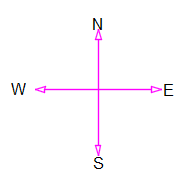
N =North
S = South
E = East
W = West
अगर ड्राइंग में दिए गये दिशा को अपने body पे सेट किया जय तो सामने की तरफ north पीछे की तरफ south right hand की तरफ east और left hand की तरफ west होगा और सिरके तरफ up और पैर की तरफ down होगा
If the direction given in the drawing is set on your body, then the north will be on the front, back, south, right, east, and west, and head side will be up and down on the foot.
Plan drawing 90 degrees. में होता है जैसे की आप निचे के चित्र में देख सकते है
Plan drawing 90 degrees. As you can see in the picture below.
ड्राइंग में केवल North डायरेक्शन दिखाया रहता है बाकि का दिशा हमें खुद find out करना पड़ता है जय की आप ड्राइंग में देख सकते है
Only North direction is shown in the drawing, we have to find out the other direction ourselves, you can see it in the drawing.
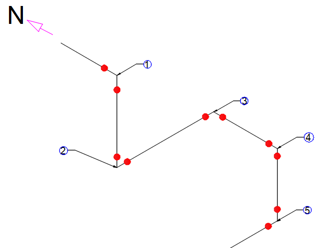
अगर आप ड्राइंग को देखेगे तो वहा पे केवल north दिशा दिखाया गया है बाकि का दिशा हमें पता करना होगा इस ड्राइंग को अगर upper से study किया जय तो लाइन नार्थ से साउथ की तरफ फिर down, डाउन से east, east से southफिर डाउन और लास्ट में डाउन से west डायरेक्शन में लाइन चला गया है और इस ड्राइंग में 90-degree का 4 एल्बो लगा हुवा है
If you look at the drawing, then only the north direction is shown there, we have to find out the other direction, if this drawing is studied from the top, then the line has gone from north to south, then down, down to east, east to south, then down and last from down to west direction. And this drawing has 4 90-degree elbows.